Polar Alignment System
For accurate tracking the axis of the platform must be aligned parallel to the Earth's axis of rotation.
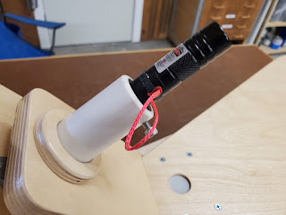
To facilitate this I added an alignment tube into which is inserted an inexpensive green laser pointer. The laser's position is calibrated using the set screws visible underneath such that its beam is exactly aligned with the platform's axis. To use it, simply rotate the platform and adjust the leveling feet until the laser beam points at the north celestial pole, which is approximately (within one degree) at the position of Polaris. |
| The laser in the socket. A black silicone rubber band (just visible) can be positioned over the pushbutton to hold it on. The pink string makes it easier to lift the band. |
The laser was $15 at Amazon. (See the 'Bill of Materials' tab in the design spreadsheet.) It recharges via USB so there is no issue with dead batteries. The diameter of the laser's base is just over 19mm. This determines the size of the hole in the back of the mounting socket. The tube is a piece of 1" schedule 40 PVC, threaded to accept the set screws. The PVC tube is glued into the socket with thickened epoxy.
To make the socket, start with a small rectangular piece of 9mm-12mm hardwood or Baltic birch. Set up a fence and stops on the drill press so you are able to make concentric holes.
First make the socket for the PVC tube. I used a 1-3/8" Forstner bit and went about halfway through (6mm). That makes a hole that's a bit too big for the outside diameter of the 1" PVC but it's the closest I had. Then find a bit that is just larger than the laser pointer and drill all the way through to make the socket for the back of the laser pointer. My laser is just over 19mm in diameter, so I used a 20mm Forstner bit. Finally, use a hole saw to cut out the circle. I used a 2-1/4" hole saw, resulting in a socket that's just over 2" in diameter.
 |
| Drilling the laser socket after drilling the PVC socket halfway through |
 |
| Cutting out the disc |
 |
| Alignment socket. PVC tube will seat into the larger hole with glue; back of laser will rest in smaller hole. |
 |
| Socket mounting screws are outside the bearing flange |
To calibrate the beam, aim the platform's axis at a somewhat distant object like a far wall, the side of your house, or a tree. Place a heavy weight on the platform, insert the laser, turn it on, and rock the platform from side to side. Observe the point of light projected by the laser. If the beam is parallel to the platform's axis, the point will remain stationary as you rock the platform. If not, adjust the screws to realign the laser. (As you rock the platform clockwise, imagine the point moving on the face of a clock. Adjust the laser so the point moves to the center of the clock. For example, if the point moves from 4-o'clock to 5-o'clock, move the laser up and to the left.) Be aware that the beam may not be parallel to the laser pointer's aluminum body, so the beam's direction is sensitive to the orientation of the pointer in the tube. Always place it in the same position, for example with the button directly up.


Comments
Post a Comment