Platform Geometry
The platform design follows the outline from Reiner Vogel. Reading his overview will definitely help what follows make more sense. The basic idea is to customize the platform to meet these criteria:
- The inclination of the platform's axis of rotation should correspond to the latitude where the platform will be used.
- To minimize the torque required to rotate the platform, the combined center of mass of the rotating elements (the telescope, its base, and the rotating platform base) should be located on the axis of rotation. This determines the longitudinal (north/south) position of the telescope on the platform.
- For stability, the circular segment that the platform rotates on should be approximately under the telescope's feet. This determines the longitudinal position of the circular segment, which in turn determines its radius as the perpendicular distance to the axis.
- The length (chord) of the circular segment should match the width of the telescope base at its feet. This determines the width of the circular segment under the platform, and the width of the platform itself.
A platform for low-ish latitude and high-ish center of mass leads to a long platform. To shorten the platform, instead of being located on the reference plane at the conical vertex, the south bearing can be elevated on a support structure that intersects the axis.
We need a diagram! and a spreadsheet! to visualize all this and compute the measurements. There was a spreadsheet somewhere linked indirectly from Reiner's site but the link seems to be broken. So I adapted Reiner's diagrams, and created my own spreadsheet. If you want to edit the spreadsheet, you'll need to make a copy (on the main menu: File --> Make Copy). In the spreadsheet, refer to the tab labeled 'Geometry'.
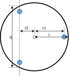
This diagram is a top-down view of the telescope's base. This assumes a typical Dobsonian telescope that has a triangular foundation with 3 feet, and a "lazy-susan" style base. The idea is to build the platform such that it supports the feet as directly as possible. The measurements of interest are the total radius (r) of the base, which determines the size of the platform, and the position of the feet (r1) and (r2), depicted as blue circles.
This is a schematic elevation view of the platform looking from the west, adapted from Reiner Vogel.
Note that in this diagram the reference plane is the bottom of the platform rather than the top. This helped facilitate the measurements during construction.
The first section on the Geometry tab calculates the position of the combined center of mass (CoM) for the telescope and platform (h). The vertical line from where the CoM intersects the rotational axis is called the Azimuth Axis (AA) and serves as the reference point for measuring the other positions. The second section calculates the position (b-a), radius (c), and width (cs) of the circular segment to meet the criteria above. The third section calculates the horizontal (x) and vertical (z) position of the south bearing.
These dimensions are used as follows in the construction of the platform:
- Cut the beveled circular segment so that its outside (north) face has radius (c) and width (cs).
- Bevel the south end of the platform.
- On the bottom of the platform, measure the distance (x) + (b-a) to mark the position of the circular segment. Mount the circular segment.
- On the south bearing riser piece (slanted yellow piece on the right), from the bottom edge of the platform, mark the position of the bearing axis at distance (z). Mount the riser to the platform.
- Mount rollers under the circular segment and the south bearing centered on the marked location.


Comments
Post a Comment