Finishing Out the Platform
Now that the platform is complete, it's time for some finishing touches. Obviously nothing here is essential. I'll describe what I did; you can certainly adapt any part of it to your own needs and tastes.
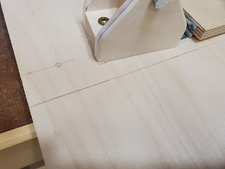
On the base, mark the locations of the 3 leveling feet at the front (north) corners and in the center of the back (south) edge. Mark a line across the front and back where you will trim the base to length. Mark diagonal lines from near the front to the back if you want to trim the base to a trapezoidal shape.
Drill holes for the feet. My feet have M10 shafts so I drilled 10mm holes. I'll talk about the feet themselves below.
On the platform above, mark a length line above the one on the base below, and mark diagonal lines to the bearing riser to form a trapezoidal shape for the platform.
 |
| Front cut line and leveling foot location |
 |
| Duplicate the front cut line on the platform |
 |
| Diagonal cut lines |
Completely disassemble the platform. Cut the lines, and round all the corners and edges. For the corners I used a trim router with a top-bearing flush cut bit and a 3/4" radius template (1/2" for the smaller pieces). For the edges I used a trim router with a 1/8" radius round-over bit.
 |
| Lines cut, corners and edges rounded. The square hole in the bearing base is for the display. |
 |
| Masking the glue surface for the support blocks |
For the finish I used a clear water-based polyurethane called General Finishes High Performance in semi-gloss. I've used this finish before and I find it to be very user-friendly and give great results. I sprayed the larger pieces and brushed the smaller ones. I did two coats, sanding between with 320-grit paper.
I got some M10 star knobs, also from Amazon, and screwed them to the top of the threaded shaft on the feet. I used the nuts supplied with the feet as jam nuts against the knobs to lock them to the shafts. I found the platform to be a bit wobbly with just the legs threaded into the T-nuts so I added wing nuts on top. The process to raise or lower a foot is: loosen the wing nut 1/2 turn; turn the knob; tighten the wing nut.
 |
| The hex nut jams against the knob by turning it counterclockwise (up), which locks the knob to the shaft |
 |
| Just for looks |
I mounted a compass and 2D level to the platform for rough polar alignment.


Comments
Post a Comment