Posts

Overview

Image
This blog is about an equatorial tracking platform I built for my son's 10" Dobsonian telescope. (A tracking capability for a telescope allows it to track the motion of the stars as the Earth rotates, avoiding the need to constantly reposition the telescope. Large reflectors like Dobsonians typically lack tracking.) When we got the telescope we quickly realized that tracking would be a great enhancement, so I got to work. I worked hard on it and learned a lot, and I'm very satisfied with the result. I thought I'd try to document my effort in case it's useful to someone else, hence this blog.

User's Guide

Image
Orient the platform roughly level and roughly facing north.

Platform Geometry

Image
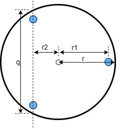
The platform design follows the outline from Reiner Vogel . Reading his overview will definitely help what follows make more sense. The basic idea is to customize the platform to meet these criteria:

Construction Basics

Image
The remainder of this blog details the construction of the platform in case someone wants to build one like it, or just get ideas. This post is a general overview of the construction process; subsequent posts provide detail on various subsystems.

Building the Circular Segment

Image
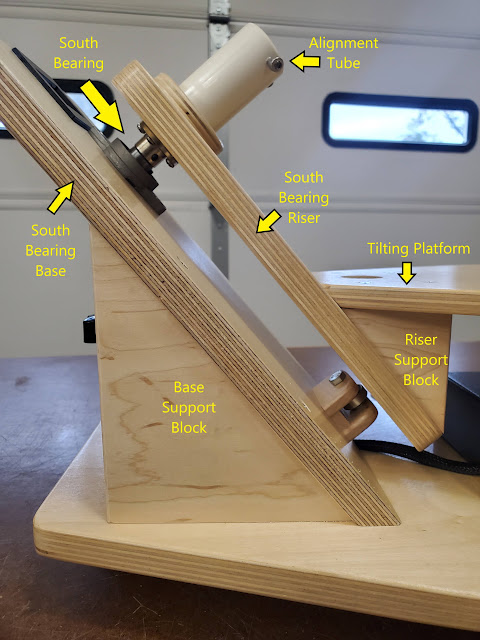
The crux of this particular design is the beveled circular segment which provides a horizontal bearing surface for the platform's bearings and drive.

Building the Platform

Image
The previous post covered construction of the platform's circular segment. This one covers the rest of the physical platform, excluding the drive and electronics.

The Drive Assembly and Engagement Mechanism

Image
The drive for my platform consists of a stepper motor coupled to a 100:1 planetary gearbox which turns a urethane roller in contact with the bearing surface of the circular segment. Pressure between the roller and the bearing surface is maintained by a spring under the base on which the motor is mounted.

Finishing Out the Platform

Image
 Now that the platform is complete, it's time for some finishing touches. Obviously nothing here is essential.  I'll describe what I did; you can certainly adapt any part of it to your own needs and tastes.

Polar Alignment System

Image
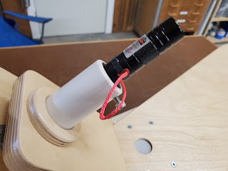
For accurate tracking the axis of the platform must be aligned parallel to the Earth's axis of rotation.

Electronics

Image
Design Considerations Sophisticated electronics are not a requirement for an EQ platform. All that is needed is an accurate way to drive the motor at a constant speed.

Updating the software

Image
If you wish to change the behavior of the platform by modifying the software in the Arduino controller, this page provides step-by-step instructions.

Final Thoughts

 Overall, I'm pretty happy with how this turned out. To test the platform, I set it up and aimed it at Jupiter. I used the hand controller to put the edge of planet's disc right at the edge of the field of view. It stayed right there, edge-to-edge, for over 20 minutes. Jupiter's angular diameter is currently about 40 arcseconds. I think I can claim that the platform drifts much less than 1 arcsecond per minute. And with the controller it should be easy to make any compensations. I was hoping to try some imaging but due to lack of both knowledge and opportunity I was not able to do that. The platform is built for 40 °N latitude  but I am at just under 30 °  so I had to elevate the south end by over 10 ° , which moves the center of gravity significantly off the axis of rotation. Even with that instability the platform had no trouble maintaining robust rotation. As long as Polaris is in view, the polar alignment with the laser is super easy. It took less than 60 seconds. The d